clarkpark
Member
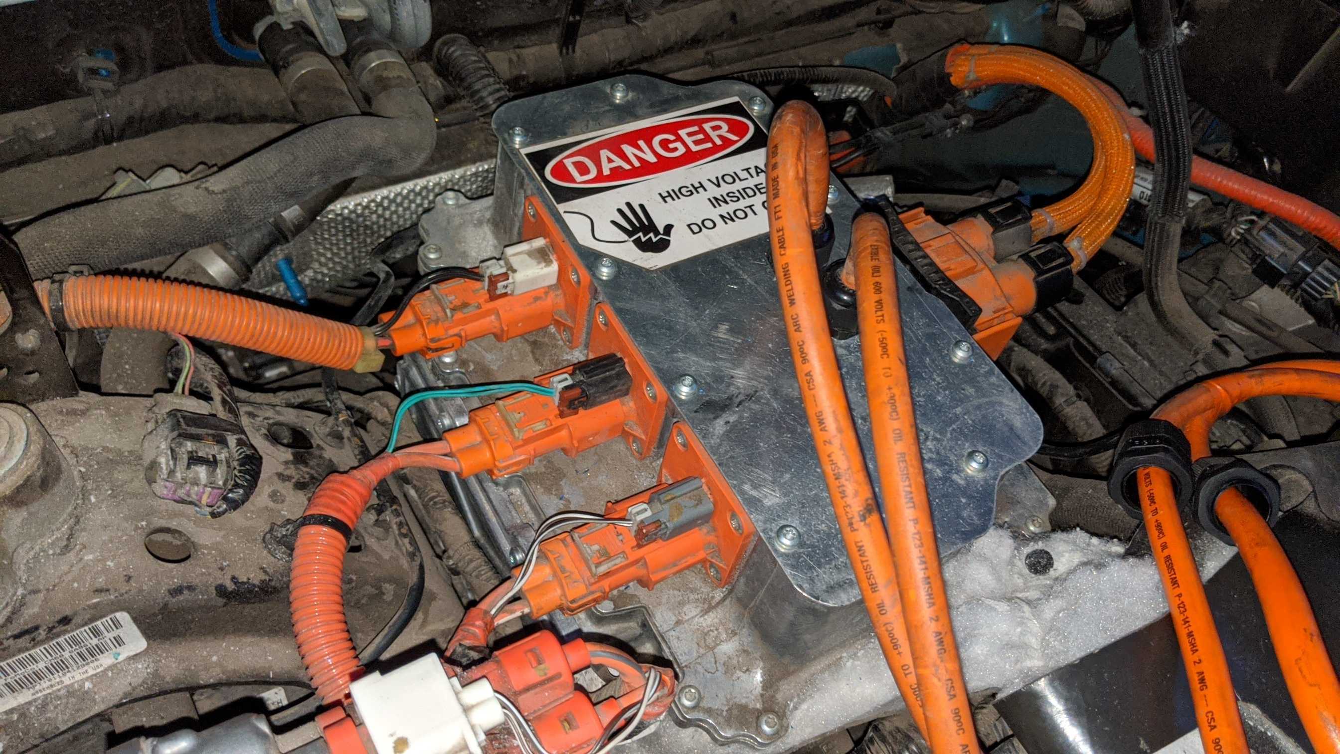
Our 2016 FFE is dead with SSN error that will not clear. Here is what I get from ForScan:
Code: P0A0A - High Voltage System Interlock Circuit 'A'
Additional Fault Symptom") 01):
01):
- General Electrical Failure
Status (-8F):
- DTC Present at Time of Request
- Malfunction Indicator Lamp is On for this DTC
Module: Powertrain Control Module
Freeze Frame #1:
-TOTAL_DISTANCE: 69466 km - Total Distance
-MODULE_VOLTAGE: 11.8 V - Control Module Voltage
-OUTDOOR_TEMPERATURE: 14 °C - Outside temperature
I understand that this could be a loose connector causing this problem. Are there instructions where to find these connections before I have it towed to the dealer?
The car first went on sale in Jan 2016 but didn't actually get sold until 2017. Not sure if Ford will honor the warranty or not.
Thanks in advance for any tips!
Clark
Code: P0A0A - High Voltage System Interlock Circuit 'A'
Additional Fault Symptom
01):- General Electrical Failure
Status (-8F):
- DTC Present at Time of Request
- Malfunction Indicator Lamp is On for this DTC
Module: Powertrain Control Module
Freeze Frame #1:
-TOTAL_DISTANCE: 69466 km - Total Distance
-MODULE_VOLTAGE: 11.8 V - Control Module Voltage
-OUTDOOR_TEMPERATURE: 14 °C - Outside temperature
I understand that this could be a loose connector causing this problem. Are there instructions where to find these connections before I have it towed to the dealer?
The car first went on sale in Jan 2016 but didn't actually get sold until 2017. Not sure if Ford will honor the warranty or not.
Thanks in advance for any tips!
Clark


![20240607_110359[1].jpg](https://cdn.imagearchive.com/myfocuselectric/data/attachments/0/96-375a31b6188b63185ac0ef9465038509.jpg)