
You are using an out of date browser. It may not display this or other websites correctly.
You should upgrade or use an alternative browser.
You should upgrade or use an alternative browser.
PERFORMANCE TUNING ANYONE?
- Thread starter lotusman
- Start date


Help Support Ford Focus Electric Forum:
This site may earn a commission from merchant affiliate
links, including eBay, Amazon, and others.
triangles
Well-known member
From what I remember of my 65 hp Chevette, it would give the FFE a run for it's money off the line. However the FFE would quickly blow it away once it got rolling. I'm often surprised how slow the FFE is off the line and by how quick it is once rolling. With only 49% of the weight on the drive wheels and even less once weight shifts rearward during acceleration, it's no surprise the FFE is slow off the line and prone to wheel spin. It would be nice if ford had tuned it so that you could ride the line of just spinning the wheels, but I understand why they didn't. I imagine that since the driver has less wheel spin feedback (ie you can't tell nearly as well how much wheels spin you have in a FFE vs ICE), you would get much more wheel spin than if it were an ICE vehicle. I could see this excessive wheel spin destroying the differential in short order and ford would be replacing them under warranty left and right. So while I don't like it, I think Ford did the right thing here.rsanders4 said:A Leaf will smoke a Focus EV off the line, hands down.
skyguy_6153
Well-known member
If you want control over the motor, you're gonna need to gain control of the brain of the car, or the inverter. In the FFE, I think its the TCM, or the Transmission Control Module. If you take off the plastic motor cover under the hood, the first thing you'll see is the TCM. Most likely, the software for the TCM is not open to the public, so their is only really two ways of getting the TCM to bend to your will. :twisted:
The First way is by getting rid of the logic board in the TCM/inverter ( which more than likely has a closed system, and design something that you can program, and install it in its place. This way, you'll have access since you're going to be in control of the brain.
The second way, and probably more easier to do, is you have to use some sort of tool (like CAN sniffer of some sort) to read the communication that goes in and out between the TCM/inverter and the ECU. And once you recognize and isolate the commands in between, then you can develop another system that speaks that same language and spits those commands out and essentially tricking the brain(TCM/inverter) that its getting the right commands from the right devices. Long story short, you can potentially gain access to the motor full potential. Below is something I pulled off a webpage that explains each part of the FFE. Ill also upload a pic to go along with this.
Or something like that :roll:
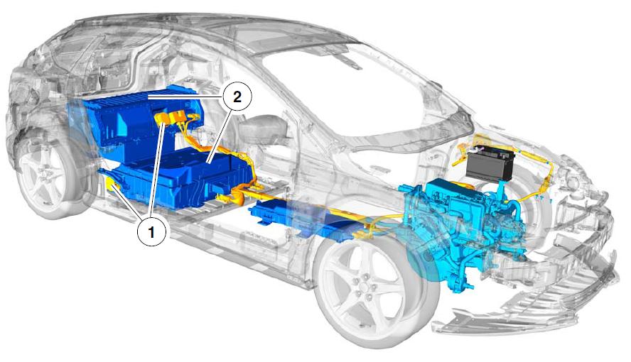
1) High-Voltage Service Disconnects- Upper disconnect is located behind the rear seatback. Lower disconnect is below the upper pack near the right
hand rear tire. Orange in color with a square body design. Uses a two stage release tab. Provides means to disconnect high-voltage batteries for safely servicing vehicle.
2) High-Voltage Battery-Located behind the rear seatback and under vehicle. Liquid cooled/heated lithium ion. Provides high-voltage storage for vehicle’s motor.
3) High-Voltage Wiring Runs along the vehicle’s floorpan from the high-voltage battery to the underhood compartment.
All high-voltage wiring has orange-colored insulation. Provides physical connection between high-voltage battery and vehicle’s high-voltage equipment.
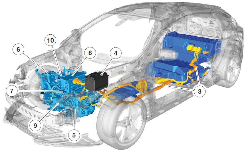
4) 12-Volt Battery-Located under the hood on the driver side of the vehicle. Typical automotive 6-cell lead/acid design. Provides 12-volts for vehicle accessories.
5) Single Speed Automatic Transmission (Gearbox)-Transverse-mounted design, similar to the non- vehicles. Attached to the traction motor Provides rotational force to the wheels for vehicle propulsion.
6) DC/DC Converter- Located under the hood on the passenger side, next to the washer solvent reservoir. Has orange high-voltage wires and Motor Electronics Cooling System hoses attached to it. Provides 12 volts to charge the 12-volt battery and run vehicle accessories.
7) Motor -Liquid cooled 3-phase AC permanent magnet motor. Attached to gearbox,centrally located in the engine compartment. Turns energy from the high-voltage traction battery into movement that is applied to the transmission for vehicle propulsion.
8) Transmission Control Module(TCM)- Module located on top of the motor. Hall effect sensor type module. The TCM controls the motor/inverters to produce the desired torque output to the wheels.
9) Air Conditioning Compressor- Located in front of the motor. Has an orange high-voltage wire attached to it using an interlock connector. Replaces the belt driven air compressor.
10) PTC Heater (Cabin CoolantHeater)-Located on the RH side of the motor near the DC/DC converter. Has both low and high voltage al connections. Used to raise the temperature of the coolant to normal operating temperature
The First way is by getting rid of the logic board in the TCM/inverter ( which more than likely has a closed system, and design something that you can program, and install it in its place. This way, you'll have access since you're going to be in control of the brain.
The second way, and probably more easier to do, is you have to use some sort of tool (like CAN sniffer of some sort) to read the communication that goes in and out between the TCM/inverter and the ECU. And once you recognize and isolate the commands in between, then you can develop another system that speaks that same language and spits those commands out and essentially tricking the brain(TCM/inverter) that its getting the right commands from the right devices. Long story short, you can potentially gain access to the motor full potential. Below is something I pulled off a webpage that explains each part of the FFE. Ill also upload a pic to go along with this.
Or something like that :roll:
1) High-Voltage Service Disconnects- Upper disconnect is located behind the rear seatback. Lower disconnect is below the upper pack near the right
hand rear tire. Orange in color with a square body design. Uses a two stage release tab. Provides means to disconnect high-voltage batteries for safely servicing vehicle.
2) High-Voltage Battery-Located behind the rear seatback and under vehicle. Liquid cooled/heated lithium ion. Provides high-voltage storage for vehicle’s motor.
3) High-Voltage Wiring Runs along the vehicle’s floorpan from the high-voltage battery to the underhood compartment.
All high-voltage wiring has orange-colored insulation. Provides physical connection between high-voltage battery and vehicle’s high-voltage equipment.
4) 12-Volt Battery-Located under the hood on the driver side of the vehicle. Typical automotive 6-cell lead/acid design. Provides 12-volts for vehicle accessories.
5) Single Speed Automatic Transmission (Gearbox)-Transverse-mounted design, similar to the non- vehicles. Attached to the traction motor Provides rotational force to the wheels for vehicle propulsion.
6) DC/DC Converter- Located under the hood on the passenger side, next to the washer solvent reservoir. Has orange high-voltage wires and Motor Electronics Cooling System hoses attached to it. Provides 12 volts to charge the 12-volt battery and run vehicle accessories.
7) Motor -Liquid cooled 3-phase AC permanent magnet motor. Attached to gearbox,centrally located in the engine compartment. Turns energy from the high-voltage traction battery into movement that is applied to the transmission for vehicle propulsion.
8) Transmission Control Module(TCM)- Module located on top of the motor. Hall effect sensor type module. The TCM controls the motor/inverters to produce the desired torque output to the wheels.
9) Air Conditioning Compressor- Located in front of the motor. Has an orange high-voltage wire attached to it using an interlock connector. Replaces the belt driven air compressor.
10) PTC Heater (Cabin CoolantHeater)-Located on the RH side of the motor near the DC/DC converter. Has both low and high voltage al connections. Used to raise the temperature of the coolant to normal operating temperature
The original question was whether anyone has done any performance tuning. I think the FFE can perform better off the line, but what personally bugs the HELL out of me is that the car has a speed limiter. It's MY car - I will decide how fast I want to go (wtf). Not only that, but some freeways have a speed limits of 75, so people frequently drive 85+. Every now and then you need to pass them to get into the correct lane.
Has anyone taken their FFE in to a performance shop with an ODB programmer? I think that's the method to remove the speed limiter on many gas engine cars. Maybe Ford was lazy and stuck it in the same place?
Norm
Has anyone taken their FFE in to a performance shop with an ODB programmer? I think that's the method to remove the speed limiter on many gas engine cars. Maybe Ford was lazy and stuck it in the same place?
Norm
skyguy_6153
Well-known member
Think less gas performance and more electric performance. Basically, how do you make an RC car go faster? You increase the voltage. Same goes for an electric car.
normanrs said:I think the FFE can perform better off the line, but what personally bugs the HELL out of me is that the car has a speed limiter. It's MY car - I will decide how fast I want to go (wtf).
I imagine the speed limiter setting has more to do with electricity and induction, but I'm no electrical engineer. I agree that it is just on the edge of acceptability for highway driving.


$42.99
$49.99
MODILOVER Car Floor Mat, Compatible with 2011-2015 Ford Focus, Nylon Black Floor Liner Carpet Set, 4PCS
MODILOVER


NavinRJohnson
Active member
- Joined
- Nov 4, 2014
- Messages
- 42
normanrs said:The original question was whether anyone has done any performance tuning. I think the FFE can perform better off the line, but what personally bugs the HELL out of me is that the car has a speed limiter. It's MY car - I will decide how fast I want to go (wtf). Not only that, but some freeways have a speed limits of 75, so people frequently drive 85+. Every now and then you need to pass them to get into the correct lane.
Has anyone taken their FFE in to a performance shop with an ODB programmer? I think that's the method to remove the speed limiter on many gas engine cars. Maybe Ford was lazy and stuck it in the same place?
Norm
Norm, you and me both. Hopefully a tinkerer can figure that out. I'm sure there's some $$ to be made for whoever does.
Car works fine for me, I don't drive over 80MPH much at all. Long distances maybe but under those circumstances I'd be the ******* doing 60 in the right lane to save power... not enough battery to warrant driving 80+ (and I don't go from 40 to 80, then come off a ramp, 80 is one of those speeds I settle into after minutes of finding the right spot & lane on the highway when I know I have a long way to drive).
The only thing that does bug me is the way it's limited below 20MPH. I do appreciate the limiter (to avoid chewing up the tires too soon) but it should be set to ~8-10MPH not 20.
The only thing that does bug me is the way it's limited below 20MPH. I do appreciate the limiter (to avoid chewing up the tires too soon) but it should be set to ~8-10MPH not 20.
skyguy_6153
Well-known member
Gain control of the inverter, you gain control of the motor. There's a reason why a inverter/motor controller is called a controller. It tells the motor how much power to put down.
Similar threads
- Replies
- 22
- Views
- 34K
- Replies
- 10
- Views
- 19K
- Replies
- 40
- Views
- 30K