skyguy_6153
Well-known member
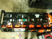
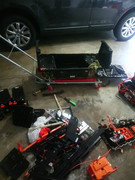
In follow up to my previous post (where I removed the upper HV battery pack), I'll post this so you can at least have an idea on how to disassemble the battery pack. Make sure you have some insulated tools or if you can't afford those, just wrap them in electrical tape. It has been some time since I have worked on the battery, so most of what I'm posting is off my memory. Please be aware you are dealing with high voltage around 360 Volts, and this can potentially kill you. *** Have a phone or camera handy and remember to take plenty of pictures, as there is a lot of wires/ connectors that MUST go in their designated spots!*** Once again, Thanks to Tareq Awad and Sebastian Zuzga on the FFE facebook group for the guidance and help with this!
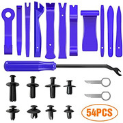
- Plastic pry tools
-
- Ratchet set, preferably an insulated one, but a metal one wrapped in electrical tape is fine
- A thick and long flathead screwdriver or small crowbar
- Engine Hoist and load leveler (harbor freight sells these for cheap https://www.harborfreight.com/1-ton-capacity-foldable-shop-crane-61858.html
https://www.harborfreight.com/3-4-quarter-ton-capacity-heavy-duty-load-leveler-67441.html
- Silver and black sharpies
- Electrical Tape
- Screwdrivers
- Duct Tape
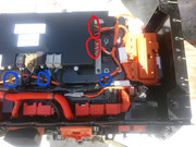
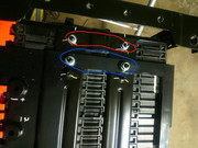
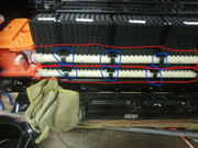
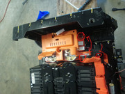
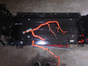
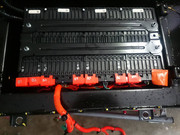
1. With the pack removed, take off the casing bolts for the "lid" (I circled them in green) When you take those bolts off, the lid should be able to just lift out ( You may need to pry it up though). Next is to take the front panels off. Be careful when you take off the two front panels (don't just yank it off). What I've circled in blue has a tiny low voltage connector behind it, and in red has two busbars for the HV connection (most likely what is supposed to go to the lower pack). When you remove the main bolts for the panel they're connected to, it won't just fall off as it'll be held by those low voltage connectors and 2 busbars.
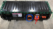
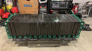
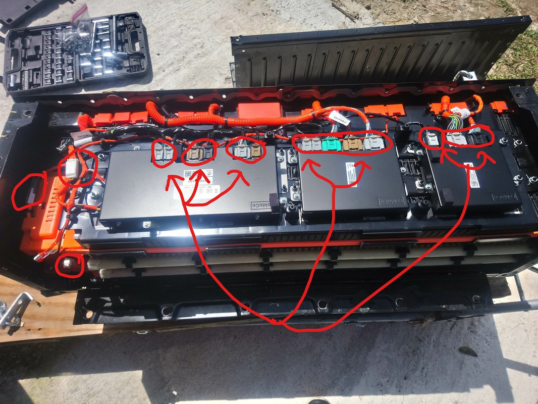
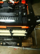
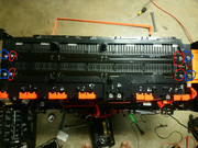
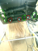
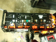
2. With the lid out of the way, (Going from left to right in the picture is the BECM, BPSM #1 and BPSM #2 ) remove the connections going to the BECM (Battery Energy Control Module), and BPSM #1 and #2 (Battery Pack Sensing Module). I circled those in red. Don't forget the connectors on the side of BPSM #2. You may need to also use a PLASTIC prying tool to pop up the cable covers from the sides of the modules (see picture 3 to know what I'm talking about, circled in red).
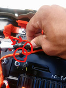
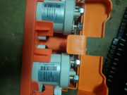
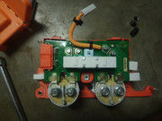
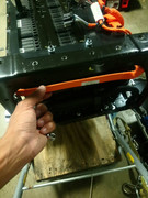
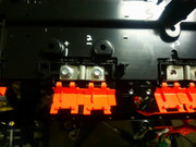
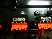
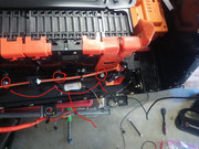
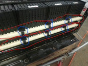
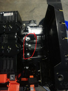
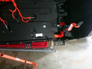
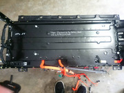
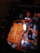
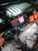
3. Now we are gonna focus on the two busbars under the big orange terminal cover. Keep your pry tool, electrical tape, and insulated ratchet handy (remember you can wrap the your non insulated one in electric tape, along with wrapping the socket in electrical tape too if you don't have proper insulated tools. I'd rather take my chances with a ratchet wrapped in electrical tape over a bare metal one!)! For this, you'll pop the terminal cover off (make sure not to break the plastic terminal cover, as it shields the terminal. Use a pry tool to remove it, if possible.). Once the cover has been removed, I recommend something that's made out of plastic, a hard rubber, or some other non-conductive material that's thin enough to fit between the two busbars, for added protection when removing the bolts from the module(s)/ busbar(s) (See pics 2 and 3, I used cut the plastic cap off a candle wax container I got at Walmart for $2. In pic 3, I circled it in blue). Make sure to take off the two bolts one by one, and watch your hands/ratchet placement. Once removed, move the wires that were held in place away from the module terminals (should be a orange wire on one, and a purple wire on the other...well at least for the 2012 FFE that is), move the busbars out the way, put the plastic orange terminal cover back on and close it in place. Now, if the busbars are dry, tape the exposed metal part of it up with electrical tape.
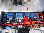
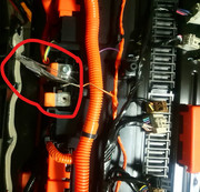
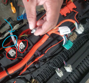
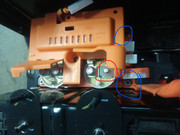
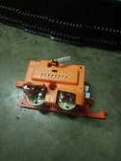
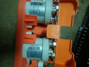
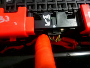
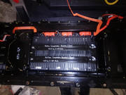
4. Now it's time to do the contactor box. In the second pic, notice in 2 red circles on the orange contactor box are connectors. Unplug those and in 2 other red circles are come wires held in place. Use the pry tool to pop those out of place, if possible. In blue circles, are just two of 4 bolts ( if I remember correctly) that hold the box in place. There is also a tiny bolt holding the contactor down, in the center of the box. I've drawn a blue arrow to show this. Next to that blue arrow (to the left of it) is a connector that I forgot to circle, pop it up off the box and disconnect it. Be careful, that particular connector is tricky, and can be easily broken.
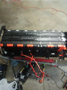
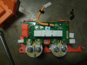
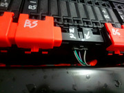
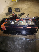
In the third pic, we are focusing on taking off the long busbar attached to the contactor (TAKE OFF FROM THE PACK FIRST, NOT THE CONTACTOR. It's the bolted down busbar circled in blue. I also partially circled one of the little holders the busbar is seated in on the back of the battery pack in red).
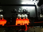
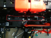
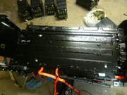
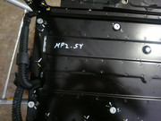
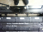
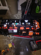
The Fourth pic shows where the busbar connects too. If you follow the busbar from the contactor, you'll see it connects to the other side of the pack. ***Make sure you are using an insulated/ electrical tape wrapped ratchet and extension (if you're using an extension, be mindful of the metal battery casing.*** Remove the bolt holding it in place, move the busbar, and close the orange cover back down. If the exposed part isn't wet, wrap it in electrical tape.
With that off remove the bolt holding the busbar to the contactor, and take the busbar out the case. Make sure to set it somewhere where it can't get bent up! Inspect the busbar, and make sure there isn't any signs of coolant that leaked onto it. If so, you'll to wipe the coolant of it, or let it dry somewhere.
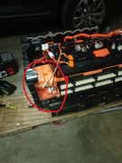
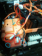
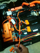
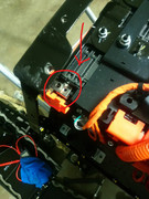
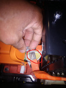
5. Remove the 2 busbars next to the one we just took off (In the first pic they are circled in red, the one we just removed is circled in blue). Follow those 2 busbars to the right front panel (3rd pic shows the path). In order to remove that panel, you'll need to disconnect the 2 mini connectors behind it (see the 5th and 6th pics. Notice the hidden wire in the 6th pic, circled in blue with an arrow pointed to it. Disconnect that also.) The 4th pic shows what I think is the current sensor, as you can probably see now (and will most definitely see in later pics on this post) it's drenched in coolant. I don't think the BECM and BPSMs were too happy about that :lol: . Notice to the left of my hand, on the black housing of the current sensor there is a tiny screw. That needs to be removed, and make sure not to lose that screw! Also unplug it's connector.
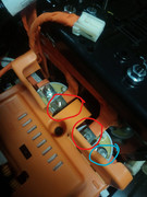
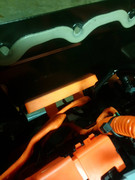
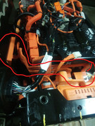
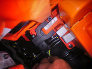
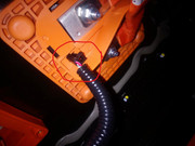
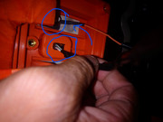
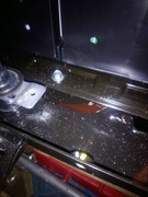
6. (****MAKE SURE YOU TAKE PICS, DON'T WANT TO MIX THE WIRING UP****) Notice how I circled the plastic cover on pic 1. Under it is a busbar, which has a wire secured beneath the bolt. Disconnect the bolt and remove that wire. Now it's time to remove the balance wires. In the 4th pic, in red I circled the balance cables that need to be disconnected. In blue, the plugs that hold said wires in place. Remove those for all the modules visible. Be careful with the half sized module ( and some of the bigger modules which have thermistors, or resistors that use resistance to measure temperature) that has the orange face cover, it's thermistor can pop out of place. The thermistor looks like a skinny small black stick and is held in place with kapton tape.
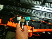
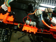
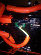
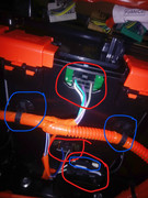
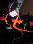
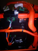
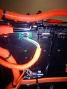
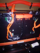
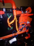
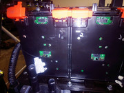
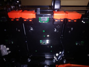
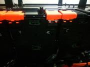
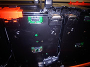
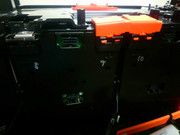
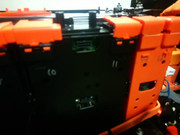
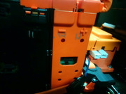
7. In these pics you can see where the coolant drenched my current sensor, and you can see a visible puddle of coolant in the case :shock: . I had to remove the busbars, wipe them off, and let them air dry (It had plenty of time to dry out as it took me roughly 2 weeks to rebuild the pack, due to me being in school and having a part time job).
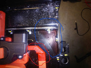
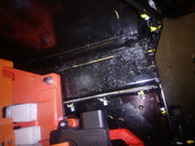
8. With the balance wires out of the way, you should be able to fully move the top part of the wire harness out of the way. The bottom stack of modules are still connected to it though, so you can just safely dangle it to the side for now. Now you can begin labeling the modules. I labeled mines with numbers so I know how they go back in the car. Make sure to have labels on (BOTH) the visible parts of the modules. With those labeled, begin removing the busbars that are connecting the modules in series. ***Do each series connection one by one!*** Every time you finish removing a busbar, close the plastic cap back down over the terminal and move on to the next one.


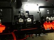
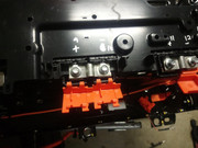
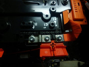
9. In pics 1 through 3, notice how I circled some bolts blue, and some red. The blue is for the plastic bracket the BECM and BPSMs sit on, red is for the battery compression bracket bars. Remove the bolts for both. Pics 4 through 6 focus on the bar that holds the modules in place, remove those bolts. Pics 10 through 12 deal with the cooling system. In red I've circled the cooling lines, and in blue I have circled the little brackets that hold the lines together. Remove the brackets, then the lines. On pic 12, in green is what the cooling lines connect to. Remove those, and there connection to the lower half of the pack. These won't be used anymore. Pics 13 and 14 show the remaining bolts holding down the coolant lines, along with the tiny bolt for the current sensor. Remove these and pull out the contactor box. Pic 15 shows one side of the compression bracket (side that the contactor box sat on. Remove those, along with the ones holding the compression bracket that was near the coolant lines. Now you'll need something very sturdy to be able to pry up the compression bars (this part can be very stressing, as the bars are in place tight. I used a thick and long flathead screwdriver to do the job). Once that's off, you can begin removing the battery modules the upper stack.
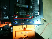
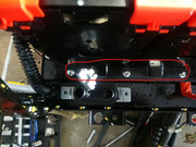
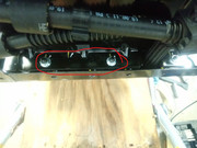
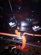
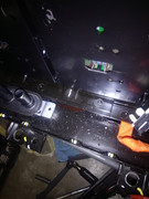
Now that is a lot of leaked coolant :shock:

10. With modules out, clean them off. You may still see coolant leaking from the plates, that is fine. Also make sure you don't sit them on the side that the coolant lines connect to. With that out the way, remove the floorboard those modules sat on. It's held in place by 8 T30 security bolts.
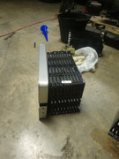
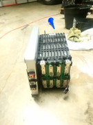
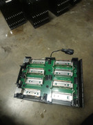
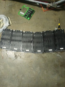
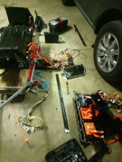
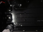
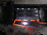
11. The bottom stack literally be taken apart and removed the same way as the top, only difference is that everything is harder to reach now :lol: . you'll need a pry tool/ some sort of flathead screwdriver to reach the connectors, and the front bracket holding the modules down will be a pain to remove. In fact I left my front bracket off on the bottom stack, due to the fact I couldn't get it to sit back down properly. I suggest taking a pic of the layout, and labeling the long busbars so you know which side goes where. And don't forget to pop off the coolant lines, brackets, and hoses. Those will be much harder tedious to do than the upper stack. KEEP YOUR TOP AND BOTTOM MODULES SEPARATE FROM EACH OTHER.
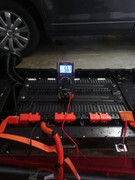
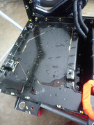
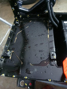
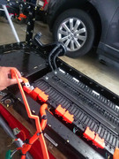
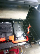
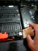
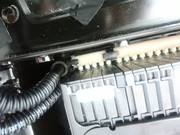
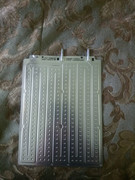
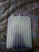
12. With everything removed you can begin to clean and dry the case, busbars, current sensor, wires, modules, etc. Now it's time to remove the heat exchangers/cooling plates between each cell. Removing the coolant plates will take away the issue of having another coolant leak (which apparently seems to be the one that keeps leaking for everyone). According to one of the FFE owners who helped me rebuild mine, the LG Chem cells only noticeably heat up when doing level 3 charging, and the first gen FFEs aren't equipped with CCS/ level 3 charging. Notice on my first pic, I've circled the first string of tabs, along with numbering the first 3 of the first string. You want to use a pry tool (PLASTIC ONLY, you'll more easily risk damage the cells with a metal tool, such as a flathead!!) to carefully pop each tab, so you can have enough room to pull out the heat exchanger. Do this for all the strings of tabs until you remove every heat exchanger from each module, and then you're ready to begin reassembly!
****Remember, you will no longer be using the heat exchangers between the modules, the cooling lines, cooling hoses, and the cooling assembly in the car Don't bother putting that back in the pack. In fact the only thing you will use again is the cooling assemblies inlet/outlet lines to make a bypass valve.****
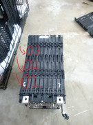
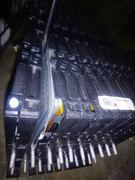
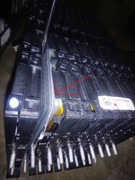
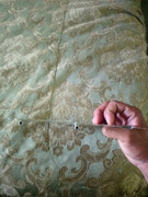
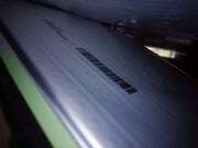
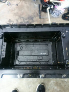
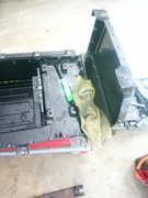
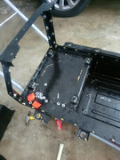
One last thing, you need to make a coolant bypass loop since coolant will no longer be flowing through the car. to do this, cut off the cooling assembling inlet/outlet hoses, take inlets to an auto parts store, have them match it up with the right size hose and clamps, and connect it to the existing hoses in the car. Look at picture 6 to see mine. In red, I circled the cooling hoses, inlet/outlet ports, clamps, and hose used for the bypass. In blue is where the inlets stick into.
-


