Quick Charge Mod - CH4D3M0

Ford Focus Electric Forum

Help Support Ford Focus Electric Forum:

This site may earn a commission from merchant affiliate links, including eBay, Amazon, and others.
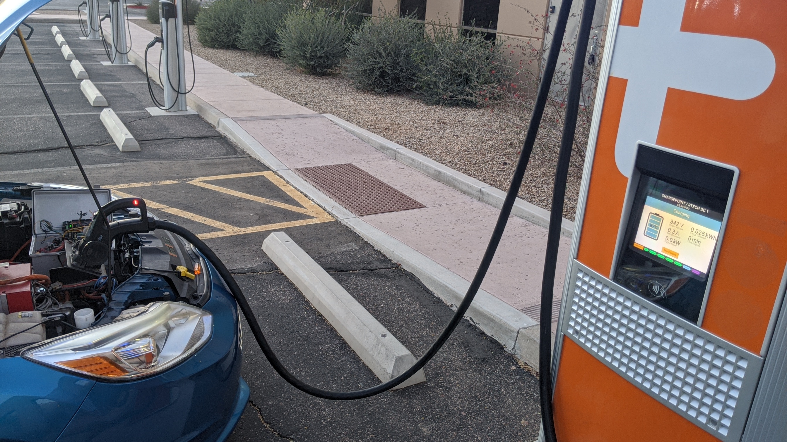
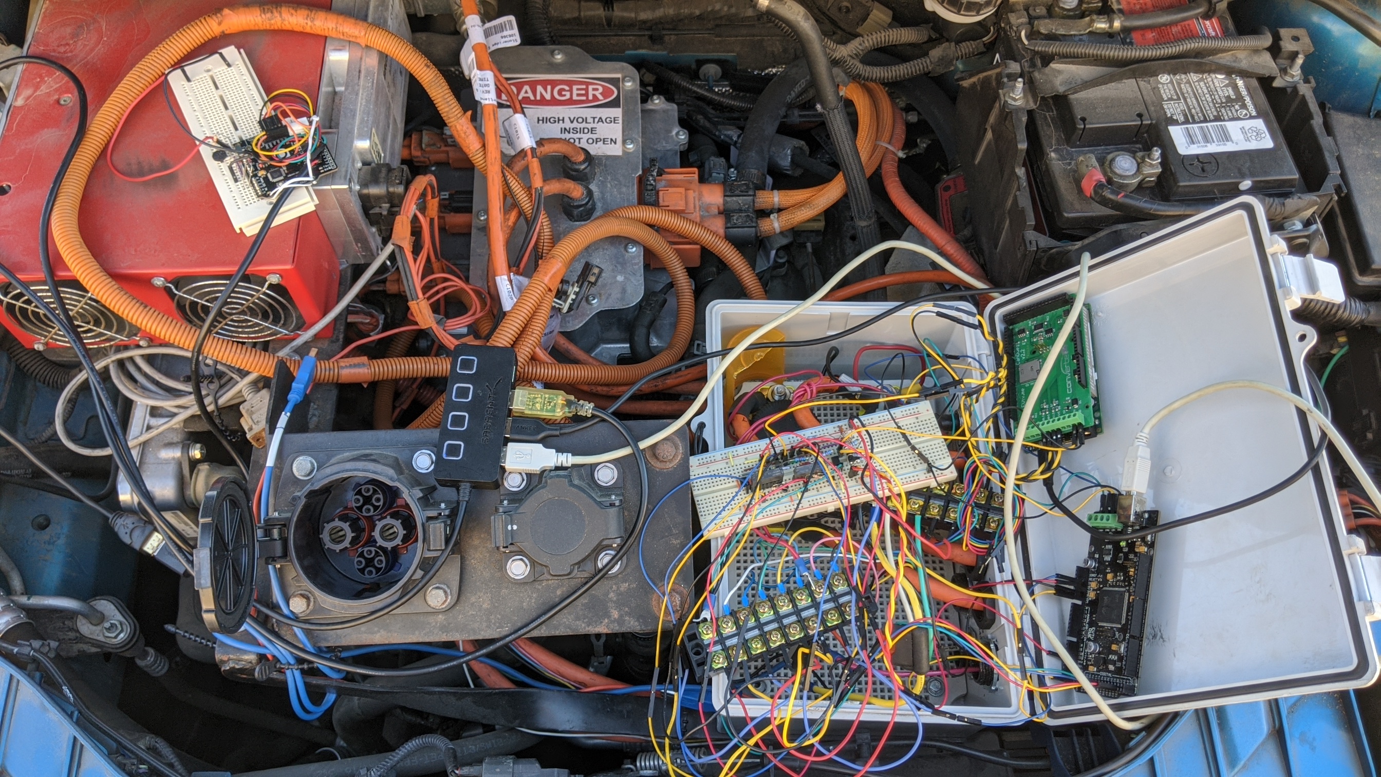
Alright. Went back with my laptop and CAN sniffing board. Aside from my board being a POS that refuses to capture two busses simultaneously, I confirmed that the charger <-> vehicle communications are occurring. The control is getting to the state where the contactors should be closing but doesn't seem to actually do so. Communication continues on the CAN loop until the charger aborts the session.

I tried to get a voltage reading from the contactor control loop but it decided it was no longer going to get that far. I have so many wires set up with extensions it's really easy for stuff to get a little loose in addition to everything getting really hot in the sun.
7EPPCMO.jpg


EDIT: Who would have guessed that in SavvyCAN, you check enable to enable CAN0 but for CAN1 you un-check enable if you want it to work too...

At least I don't have a fried CANDue shield.
 
So, I had a chance to go back to my original board design and figured out a way that I could make changes to the circuit in Eagle that would not cause the existing trace layout to change. That let me start dropping components that are no longer needed and add in jumper wires to change sections.

That will allow me to still use the three ADM3052s I bought, since I'm almost certainly not going to need them for anything else.

So, I'll be reconstructing my first board to validate that variant of the minimalist circuit and, if I get it working as expected, I can assemble the other two and sell them to some folks that want them. Since I don't need the little power supply module I originally spec'd, the total component cost is actually pretty low - maybe $30-40 between the boards and the chips. It's all just been labor, testing iterations and assembly. For my sanity, I feel like I'd need to sell them for at least $100+shipping.

So, if anyone is interested in trying to use one of these, let me know. You will need an Arduino Due, a CHAdeMO port with wiring, a set of contactors (GX12BA) and you will need to splice into your DC bus.

The version I got from Sefs bolts the wiring inside the TCM but there is no reason it can't be spliced into the harness elsewhere. You could even potentially make an in-line tap using the same connectors used on the TCM and harness - similar to this https://www.te.com/usa-en/product-YH800-2P-180-50M-A.html - and then it could be installed with effectively zero modification of the HV hardware. If you have a later model with CCS, you can also tap into the battery bus inside your EVCC case.

Though don't go buying anything until I have them really REALLY validated as working.
 
Got a chance to retry the minimalist board and I was able to actually get it to close the contactor and push current.

It was not a lot, but getting that far confirms the refactored circuit is functional and has paved the way for reworking the shields with an equivalent circuit that uses my ADM3052s.

ZAi1oPw.png
 
Back
Top