Quick charge project

Ford Focus Electric Forum

Help Support Ford Focus Electric Forum:

This site may earn a commission from merchant affiliate links, including eBay, Amazon, and others.
Sefs, it's been fascinating watching the progress on your project. It's very inspiring and helps dissuade my tendency to think of the FFE's electronics as a bunch of inscrutable black boxes wired together.

I'll bet if you're willing, someone on this forum would happily pay whatever your asking price would be for the charger setup (and perhaps sign a disclaimer promising not to electrocute themselves).

Enjoy your new ride!
 
So my main question is as I use SavvyCAN to do decoding - what IDs I need to look at to make contactron close to make battery available for charging.
 
Just compared 2 CAN sessions, IDLE and plugged in. Turns out that the only new CAN messages were 0x400, 0x405 and 0x40a. Will have to check those closer.
 
sefs ,
Can you sell your work, or show the scheme / sketch / firmware and controller?
How to add two 6.6kW inverters to the car to be charged from a 3-phase outlet?
 
OK so I have found some time to play with CAN as it gets warmer. My method is kinda brute force. I'm replaying messages previously recorded at different car state (like SOC, weather). I don't see people are willing to share the knowledge so I will do - as there is so little known about FFE CAN and everybody looks to be happy with Forscan so far.

0x178 is outside temperature - there might be some more information encoded there - I don't know what bytes do what but will find out later.

------

0x24C is SOC - when I did inject previously recorded can messages I did get this:
https://youtu.be/HW4CvpDTiCM

still don't know the bytes and stuff but will find out soon. This one alone is enough to do safe DC charging IMHO.

------

0x352 - tells about time to full charge:
https://youtu.be/cka7UdCSV_g

Sometimes I got wrench with See manual information.

------

Replaying 0x416 does this Christmas tree effect:

https://youtu.be/lmF_sN0j_7A

------

Still will be looking for individual cell voltages and other stuff like that but so far I'm closer to my solution.

Cheers
Martin
 
Dobrinia said:
sefs ,
Can you sell your work, or show the scheme / sketch / firmware and controller?
How to add two 6.6kW inverters to the car to be charged from a 3-phase outlet?

I think it was mentioned before that you can't charge faster than 11kW via AC as car will get into faulty state.
All you can add is 3.3kW charger like sefs did - otherwise you need to charge it directly when car is on (and car accepts such current as also sefs tested it already and it worked fine).

Martin
 
triangles said:
Nice work! Glad to see someone working at figuring out how things work on the FFE.

I'm using this great tool called SavvyCan - will find out soon what bytes change during charging session as now I know what ID to look at.

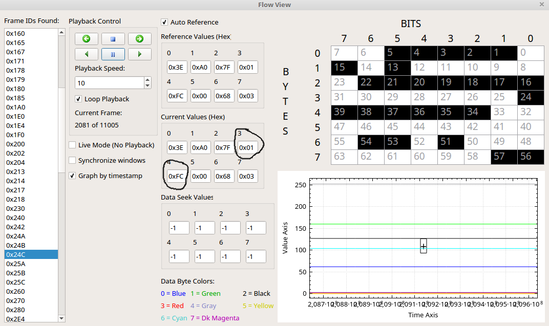
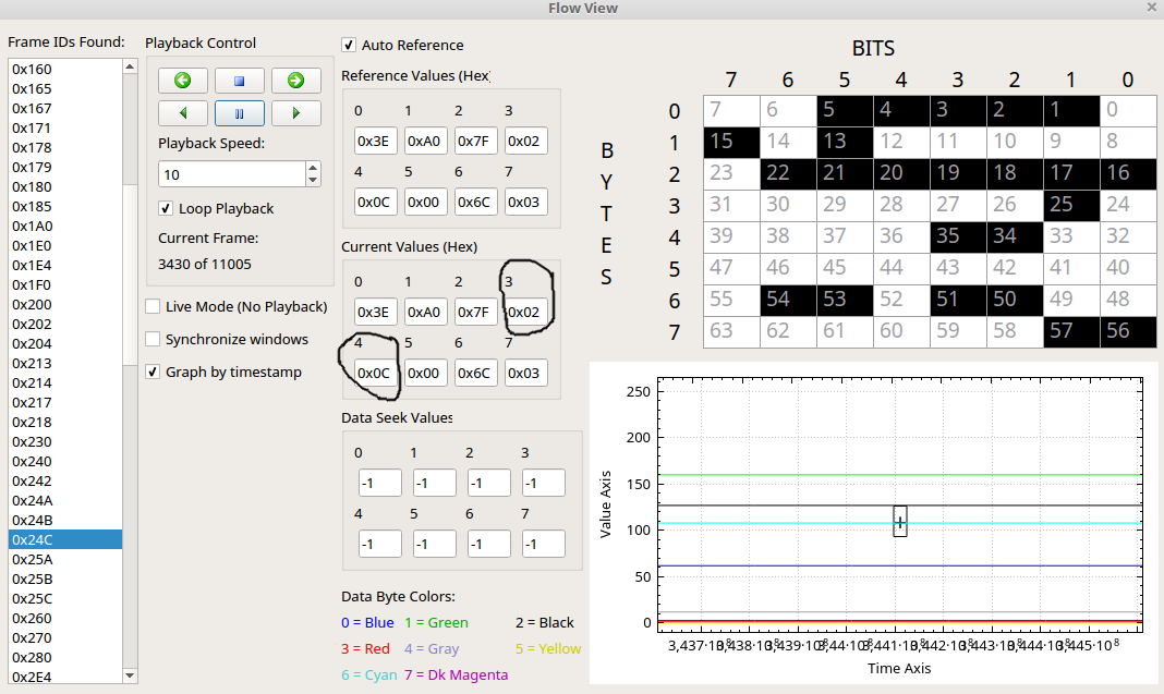
So it looks like only bytes 3 and 4 are changing during charging session. Those must be displayed capacity.

czarge1.png


B4 is counting up quickly after it comes to an limit b3 goes up and b4 starts from beginning

czarge2.png


There is something going on with B6 also. To be sure I need to look at it when car is full and empty. I have a feeling B6 might much less accurate SOC.

-------------------
edit:
-------------------

So this was CAN capture from 1100s charging session at 32A 240V.
Session started at B3 0x01 B4 0xE5 - this gives hex 01e5 = 485 decimal
Session ended at B3 0x02 B4 0x58 - this gives hex 0258 = 600 decimal

So I think true value is div. by 10 - this would give 48.5% to 60% in 1100s - looking legit.

Once again I'll check those values when car is full and empty to be 100% sure.

I don't know how many kWh went into the battery at this time but I'll find out - will be playing with this capture file and this awesome tool more.

Cheers,
Martin
 
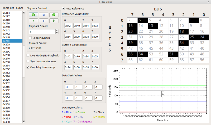
Here is fully charged car:

full.png


So car screen shows 100% charge - but:

B3 and B4 says hex 0384 = dec 900 so SOC is 90%
B6 on the other hand says hex C8 = dec 200 so div by 2 gives 100%. This must be the info car displays as no other values change that much during charging.

So now I believe B3 and B4 is real SOC as Forscan shows that cells are at 4.06V and B6 must be displayed SOC.

I'll confirm that once again when in way different SOC like closer to 10% displayed. Then I should see B6 as 14 hex.

Martin
 
Guys,

Per cell voltages (min and max actually) don’t exist on the EV CAN bus natively, only through diagnostic queries. What I did was capture what IDS was sending to get the min and max cell voltages, and then just make a for loop to constantly query that every 100 ms or so. That, as well as getting info from the charger, were the only messages I needed to query directly. Everything else I could pick up passively through the EV CAN bus.
 
martii said:
Sefs,

Can you ask for voltage of any cell or you just can get min-max?

I just read the maximum difference between the cells. So the math I did was I read the min cell voltage diagnostic parameter, and then added the maximum cell difference diagnostic parameter to get the max cell voltage. This was across the whole pack, not individually per cell. I don't remember if in IDS you could query every cell or not (I believe you could), but there is a limit to how much "active querying" you can do through the diagnostic CAN message; so it is good to limit what you are actively requesting.
 
I've been trying to sniff what Forscan does and it's sending some requests as it shows cell min voltage.

One more question - during the AC charging is the charging power given somewhere in CAN frame or I would have to calculate like amps times pack voltage?
 
martii said:
I've been trying to sniff what Forscan does and it's sending some requests as it shows cell min voltage.

One more question - during the AC charging is the charging power given somewhere in CAN frame or I would have to calculate like amps times pack voltage?

AC charging power (AC volts and AC amps) are only present through the diagnostic request. I had my display setup to request these messages when I was parked and I pressed "C". You don't want to be constantly requesting these signals while you're driving, as there really isn't a need. I had AC volts, AC amps, available amps, and AC frequency setup to be queried for. Set these up as the only messages to be queried by ForSCAN, then log the traffic. They should be in the 0x7 range. 0x7 range is reserved for the diagnostic traffic, both send and receive. I sent you a PM with some more info.
 
Back
Top