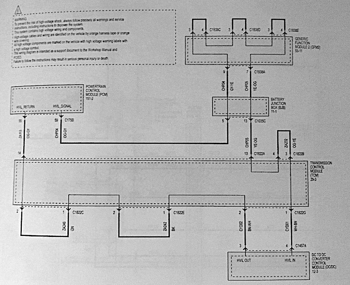
I just did a quick google search on P0A0A. So generically, when there is an HVIL failure, this code is set.
HVIL is High Voltage Interlock Loop.
I made a post a couple of weeks ago about a poorly connected high voltage connector in my 2017. In that, I talked about 2-stage high voltage connectors.
Well, for the more important high voltage connectors, the second stage has an additional set of contacts, that sense when the connector is connected or disconnected.
This separate set of wires that do not carry high voltage, but run along the with the high voltage cables, form a loop through out the vehicle. The Wiring diagram shows this best.
Anyway, whenever a high voltage connector is disconnected, the loop opens up. This open is sensed, and the high voltage system shuts down.
So imagine that you have a crummy connection for the HVIL. The car will think that a connector is becoming loose, and will shut down the high voltage as a safety precaution.
I will describe the HVIL loop as I see it in the wiring diagram.
The first loop "starts" in the PCM powertrain control module. Connector C175B pin 59
It then goes to the BJB battery junction box. Connector C1035C pin 5
It then goes to the GFM2 generic function module 2. Connector C1838A pin 9
It then loops through GFM2 connector C1838C out pin 3 and in pin 4
It then loops through GFM2 connector C1838D out pin 3 and in pin 4
It then loops through GFM2 connector C1838E out pin 3 and in pin 4
It then leaves the GFM2 connector C1838A pin 7
It then goes to the BJB connector C1035C pin 13
it then goes to the TCM transmission control module. Connect C1822A pin 13
It then loops through TCM connector C1822B out pin 4 and in pin 3
It then leaves the TCM connector C1822G pin 1
It then goes to the DCDC DC to DC converter control module. Connector C1457A pin 4, where it "ends".
The second loop "starts" in the DCDC connector C1457A pin 3.
It then goes to the TCM connector C1822G pin 2
It then loops through TCM connector C1822E out pin 1 and in pin 2
It then loops through TCM connector C1822C out pin 1 and in pin 2
It then leaves the TCM connector C1822A pin 14
And finally goes to the PCM connector C175B pin 55, where it "ends"
So by looking at this diagram, it appears that if there is a break in the HVIL, it will either be reported by the PCM or the DCDC.
It also appears that there are 12 connectors where as HVIL is sensed. This is for a 2017, so for a 2016 and earlier, it would be fewer connectors.
The connectors are:
C175B - 12v logic connector
C1035C- 12V logic connector
C1838A -
C1838C
C1838D
C1838E
C1822A
C1822B
C1822C
C1822E
C1822G
C1457A


